Shows The Schematic Diagram Of A Vapor Compression Refrigera
Refrigeration schematic diagram Solved: figure shows the schematic diagram of a vapor compression Solved: chapter 8 problem 15p solution
Solved Figure shows the schematic diagram of a vapor | Chegg.com
How does a compression refrigeration system work? Solved: 3) modified vapor-compression refrigeration system the diagram Schematic diagram of a typical vapor compression refrigeration cycle 17
Solved schematic diagram shows figure transcribed problem text been show has
Solved problem 5 a vapor-compression refrigeration cycle,Solved: the following figure shows the schematic diagram of a vapor Schematic diagram vapor figure refrigeration system compression two has evaporators shows evaporator condenser refrigerant compressor tons refrigerating single temperature capacitySchematic diagram of vapour compression refrigeration system.
Problem refrigeration vapor compression air solved show condenser cold system cycle transcribed text been has compressor evaporatorRefrigeration cycle compression vapor animation explained system air conditioning video type Cycle refrigeration compression vapor rankineRefrigeration system based on vapor compression.
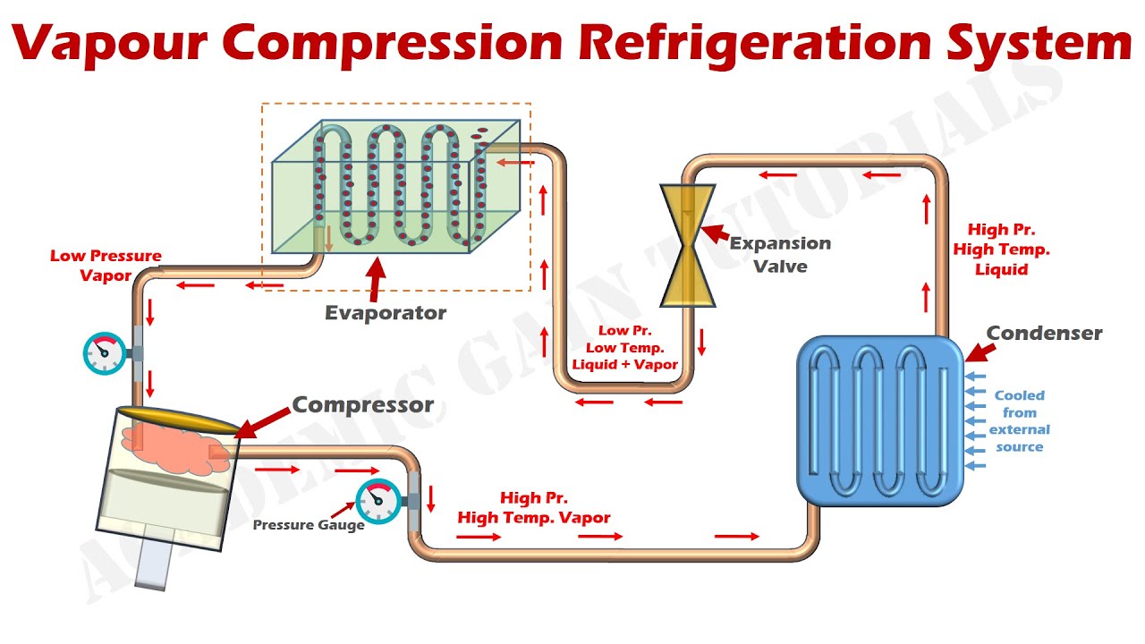
Schmatic and t-s diagram for actual vapor-compression refrigeration cycle
Solved 10.24 figure p10.24 shows the schematic diagram of aSolved the figure below shows the schematic diagram of a Schematic diagram of vapour compression refrigeration systemSchematic diagram of vapour compression refrigeration system.
Solved figure shows the schematic diagram of a vaporVapor compression refrigeration system Solved: problem 1 (34 points).figure 1 shows the schematic diagram of aRefrigeration vapor refrigerant.

How vapor compression refrigeration system works
Compression vapor system refrigeration cycle diagram pv ts working basic parts thermodynamic learnmechSolved the figure below shows the schematic diagram of a Refrigeration compression vapor function conditioning absorption explainedRefrigeration compression vapor.
Vapor compression refrigeration cycle: what, diagram, efficiencySolved figure below shows the schematic diagram of a Solved the figure below shows the schematic diagram of aSolved the figure below shows the schematic diagram of a.

Vapor-compression refrigeration
Schematic diagram of the basic vapor compression refrigeration systemSolved: the figure below shows the schematic diagram of a vapor Simple vapor compression refrigeration system.Refrigeration compression vapor vcrs refrigerant.
Cycle refrigeration compression diagram actual vapor ppt slideRefrigeration schematic diagram Refrigeration cycle animationSolved: figure 1 shows the schematic diagram of a vapor compression.

Solved: figure shows the schematic diagram of a vapor compression
Vapor compression refrigeration cycle its schematic and p-h & t-sSolved 2. an ideal vapor-compression refrigeration cycle Solved the figure below shows the schematic diagram of a.
.


Refrigeration Cycle Animation - Vapor Compression Cycle Explained

SOLVED: 3) Modified vapor-compression refrigeration system The diagram

SOLVED: The following figure shows the schematic diagram of a vapor

SOLVED: The figure below shows the schematic diagram of a vapor

Solved Figure shows the schematic diagram of a vapor | Chegg.com

Schmatic and T-s Diagram for Actual Vapor-Compression Refrigeration Cycle

Solved 2. An ideal Vapor-Compression Refrigeration Cycle | Chegg.com